Tips
Contents
Tips
Setup
- It is useful to have separate show directories for each major event i.e. one for Halloween, one for Christmas or one for the next year. Start a new year directory by copying sequences from the Show Directory of the previous year.
- You can start with a default set of network configuration values and then come back to change or update the details before testing your lights physical output.
Sequencer
- You can save the windows that you normally have open as your default perspective. These windows will then be opened when you load xLights.
- Dropping an effect on a Model group will give different results to dropping the same model on all elements of the group (because in the former case the canvas is treated as a whole matrix and then the effect is applied to the models within it). Some effects work at the Group level better than others.
- When on the sequencer tab, If you right click on a Model group, the window will display a ‘Toggle Models’ option which will display all the models under the Model group (or hide them if you select the option again). You can also double click on the Model Group to obtain the same results.
- Double Clicking on the any of the color icons opens up a Palette window, where the standard colors can then be replaced with a new standard color or a custom color can be selected.
- Effects can be stretched by using the Alt key and dragging one edge of the effect highlighted (most commonly the bottom right corner) to provide a Chase effect.You may need to use Toggle Nodes to view the nodes so as to be able to strect an effect.
- Many, but not all effect actions can be ‘Undone’ by Right Clicking on the Grid and selecting the Undo action i.e. Undo effect move or Undo delete.. etc
- Tip for using color palettes. Just click on an existing effect that has the palette you want and that will lock in the palette so that the next effect you drag and drop will inherit that palette.
- In order to control the sequence in which multiple layers are rendered, you can change the order of data layers by moving them up or down. You can similarly change the order of layers within a model. And you can also change the order of models in the master view.
Effects
- A simple way to do a chase effect is to select a block of cells and hit 'd' for a fade down or 'u' for a fade up. If you then need to adjust it, drag the end line.
- You can create Random Effects by selecting an area on the grid, Right click and selecting the option to Create Random effects. Effects will be randomly selected (along with different colors and options) and effects created in the area highlighted, each between consecutive timing marks.
- All lights off for 1/2 to a full second during an appropriate time in a sequence is powerful. When all lights come back on- KaPow! Ka-pow! as in the interpretation of the effect and not your controllers.
- Layers are your friend. Complimentary effects. I used 11 layers for this effect and followed up with bars for a complimentary transition. From here this could go to Fan/Spiral/Chase,Curtain. Example
Backup
- Pressing F10 anytime, anywhere will backup your XML files for your and store them in a zip file with the date and time the backup was created. You can press F10 as many times as you like and should do this at least once per sequencing session.
LOR Imports
- Please do not use !@#$%^&*()<>/\}{, characters in your model names. Dash works fine though. I'm helping a user move over 150 models from LOR to NC and was having issues. Getting rid of those characters solved the issue. I don't know which one of those was causing the issue but he had ,/&\ in some of the model names.
Custom Colors
From time to time you may need to tweak a color to get the lights to display a desired color. Here are some known good RGB values to start with.
- Orange1 245,48,0
- Dark Orange 255,25,0
- Purple1 102,0,60
- Purple2 75,0,130
- Purple3 105,0,255
Coming over from LOR
- Running LOR Controller in DMX Mode
LOR to DMX Channel conversion
The following table describes the conversion of a LOR Unit id to a DMX address. As an example, if you have a controller with a Unit id of 03, then when converted to run under DMX , the channel ranges will be 33 to 48.
| LOR Unit ID | DMX Address | LOR Unit ID | DMX Address |
| 01 | 1 | 11 | 257 |
| 02 | 17 | 12 | 273 |
| 03 | 33 | 13 | 289 |
| 04 | 49 | 14 | 305 |
| 05 | 65 | 15 | 321 |
| 06 | 81 | 16 | 337 |
| 07 | 97 | 17 | 353 |
| 08 | 113 | 18 | 369 |
| 09 | 129 | 19 | 385 |
| 0A | 145 | 1A | 401 |
| 0B | 161 | 1B | 417 |
| 0C | 177 | 1C | 433 |
| 0D | 193 | 1D | 449 |
| 0E | 209 | 1E | 465 |
| 0F | 225 | 1F | 481 |
| 10 | 241 | 20 | 497 |
Running LOR in DMX mode
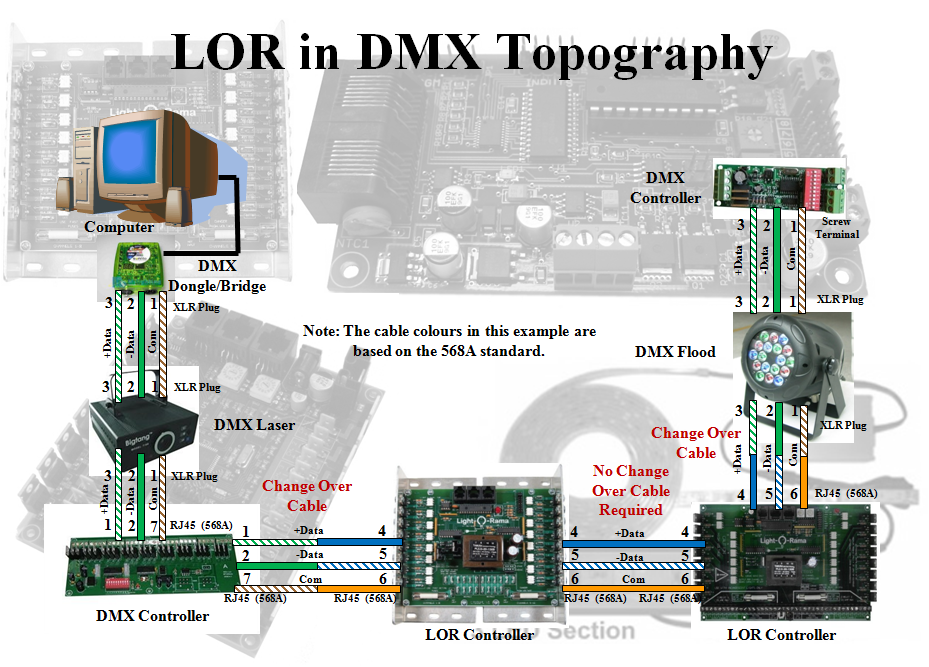
The following diagram shows an example of how LoR controllers can be connected in DMX mode. Refer to the table above of Unit ids to DMX channel conversions
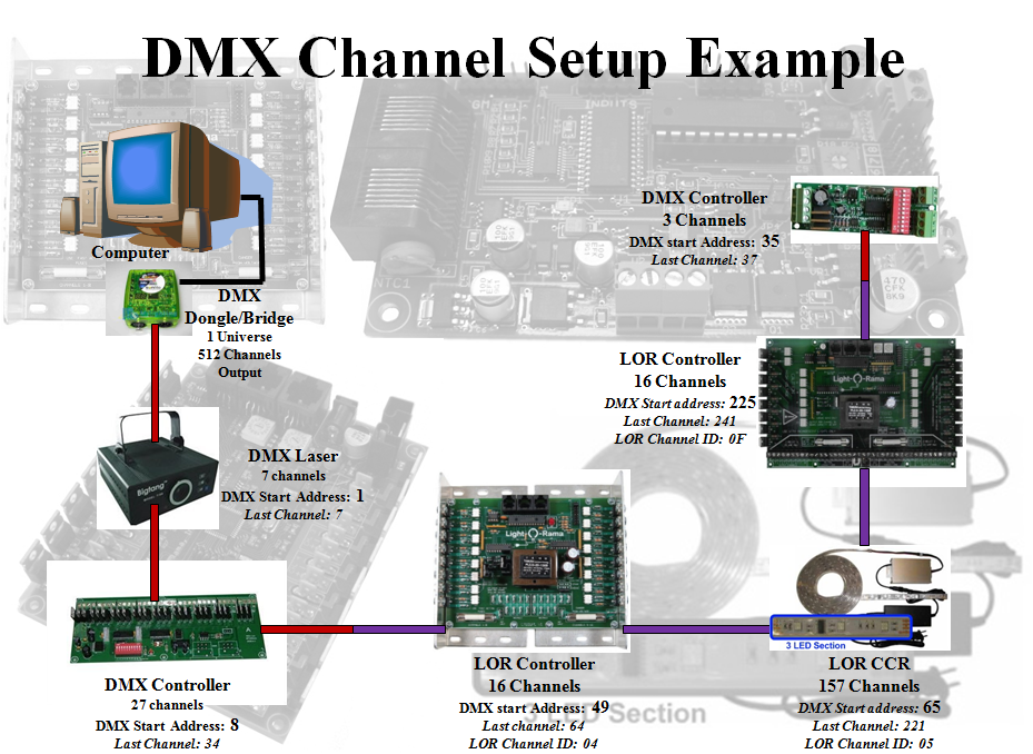
You must use the LOR hardware utility to set the DMX start address on a LOR controller if the controller doesn’t have on board channel selection. The next diagram shows an example of how LOR controller addresses are set in a DMX universe. The controllers do not need to be physically connected in order of the controllers start address. The controllers can be put in any order.
- Convert a LOR LMS file to play using non LOR hardware
This section is based on a video created by Steve Giron
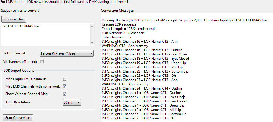
The item to be converted is a purchased 12 leg CCR tree sequence. The input file should be in LMS format. Within xLights/Nutcracker, go to the Convert tab and from there Select Convert, navigate to where the LMS file is and select it. Select the ‘Show Verbose Channel Map’ attribute. ‘Click on Start Conversion. Error messages are expected for the first run in the status window on the right side. Scroll to top of error messages and look at messages that says “LOR Network”.
The messages tell us that two networks are required: One with zero channels – (this was a star where channels were deleted from) , one with 1800 channels. Go to the Setup tab and define these. Setup tab (Existing layout)
Add two entries: Network type of LOR, any baud rate, however the last channel must map correctly. Then move them to the top using the green UP arrows.
Ensure that ‘Map Empty LMS Channels’ is not selected (else you may get errors as the CCR macros do not have effects in them). Reconvert and it should convert with no errors. Open the xseq file that was created and play it to view the effects on the layout window. You may need to click on the ‘Render All’ button. If you are not playing the sequence though LOR hardware, go back to the setup and delete the two LOR entries that you added for the conversion, leaving your previous configuration as it was. If you are using LOR hardware, then these entries will need to be correctly defined.
- Converting a LOR sequence and importing into xLights/Nutcracker.
This section is based on a video created by Clyde Lindsey
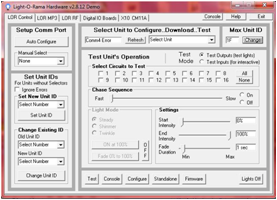
First ensure that within LOR, all the channels for the controller have been defined and are in sequence . Tools, Channel configuration will display an image similar to the following.
If there are any channels missing use the ‘Add Channels’ function to add the missing (unused) channel. 1. Note that in the image, the Unit id is 03 and the Channels (Circuit) values run from 1 to 16. However, referring to the LOR Unit Id to DMX channel m apping t able Unit id 03 corresponds to Channel number 33. If Units prior to Unit 3 have not been defined, then you need to define them so as to ‘utilise’ the missing channels. Use the ‘Insert Device’ function to ‘Insert Device Above’ the current device (Unit 03) as a LOR 16 channel device – Unit id 01. Repeat this step and add another device Unit id 02.
Therefore Channels 132 (Unit 1 and 2) have been defined – even if not required in LOR, and channels 33 – 48 belonging to Unit 03 are the ones that we are interested in.
On the xLights/Nutcracker setup screen , the corresponding channels must be defined. You can define it as a USB , with a network type of LOR , and set up the COM port (obtained from the LOR device manager) and you will need to try different baud rates.
However, there is sometimes a lag associated with the sequence when you use this option. It is preferable to use a DMX (to E131) bridge if possible and then define the channels as E131.
For the three devices were defined in LOR, only 48 channels need to be defined, but to preserve a buffer for future use, an extra 16 channels corresponding to an additional LOR device, (i.e. a total of 64 channels) will be defined in Universe 1 as E1.31.
- Model definition
Next create a new Model definition that matches the LOR Channels of Unit 03. Let’s say that this was 16 single channels Trees. In that case create a model ‘Small Tree 1’ , with 1 channel. The start channel must be set to 33 (not 1) as this corresponds to the 1 st channel of Unit 3.
Then you can copy the model, update the name (Small Tree 2) and change the starting channel to 34 and repeat this for all 16 channels, increasing the start channel by 1 each time until the last one is 48.
Tip: If within the LOR Unit 03 definition, there are unused channels, you do not have to create a model for that channel or channel range. For example, let’s say within Unit 03, channels 1014 are not used. In which case, you would create 9 Trees (1 9), and then another 2 trees (for 1516). This is different to the setup tab where you must cover the entire range of channels from 1 onwards. The next step is to use the Layout tab to align


